What goes into the design of an SCD driven pile and why it matters
Designing an SCD driven pile involves more than selecting a diameter and a depth. It requires a thorough understanding of the ground conditions, the structural loads, the installation method, and the way the pile and the surrounding soil interact during and after driving. Each of these factors influences the others, and a pile design that does not account for all of them together is one that carries more risk than it should. Understanding what the design process involves and what decisions are being made helps clients, developers, and contractors engage more meaningfully with the foundation design and avoid the assumptions that lead to problems on site.
The key design decisions involved in SCD driven piling
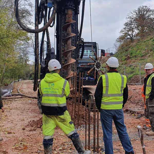
Pile diameter and length are determined by the structural loads and the ground conditions, not by convention or convenience. The casing specification, including wall thickness and steel grade, is selected to withstand the driving stresses without damage and to provide the required structural contribution to the finished pile where the casing is left in place permanently. The reinforcement cage is designed to resist the full range of forces the pile will experience in service, including axial loads, bending moments, and in some cases tension or lateral forces. The concrete specification is determined by the structural requirements and the exposure conditions in the ground. The set criterion is derived from the pile design and the ground conditions before installation begins. All of these decisions are interconnected and need to be developed together as part of a coherent design process rather than in isolation.
How the design process develops from ground investigation to pile specification
The design process begins with the ground investigation data. The geotechnical engineer interprets the investigation results and provides the soil parameters that the structural engineer uses to calculate pile capacity. The structural engineer then works through the load requirements at each pile position, calculating the diameter, length, and casing specification needed to achieve the required capacity with the appropriate factor of safety.
The reinforcement cage is designed based on the forces the pile needs to resist in service. For a straightforward axially loaded pile the cage may be relatively simple, with a modest number of longitudinal bars at moderate diameter. Where the pile is subject to lateral loading, bending from ground movement, or tension forces from uplift, the cage design becomes more detailed and the reinforcement quantities increase accordingly.
The concrete specification is determined by the structural requirements and the ground chemistry identified in the investigation. Where sulphate bearing soils or aggressive groundwater are present, the mix is modified accordingly. Where the casing is to be left in place permanently, the design accounts for the structural contribution of the steel as well as the concrete within it, which can allow a more efficient reinforcement design in some cases.
How design considerations vary across different project types and ground conditions
On a residential project with straightforward vertical loads in granular ground, the design process is relatively uncomplicated. Standard pile diameters, moderate depths, and a simple reinforcement cage will typically satisfy the structural requirements, and the set criterion provides clear in-process confirmation that each pile has been installed to the correct capacity.
On a commercial project with varying column loads, significant bending moments, or piles supporting retaining structures, the design process is considerably more involved. Different pile specifications may be required at different positions across the site, the group behaviour of closely spaced piles needs to be assessed, and the connection details between the pile heads and the ground beams or RC slabs above need to be developed in coordination with the pile design rather than treated as a separate exercise. Capital Piling's in house design team handles this coordination as a standard part of the design process, making sure the pile specification and the foundation elements above it are developed together and work as an integrated system.
The technical standards and parameters that govern SCD driven pile design
SCD driven pile design is carried out in accordance with BS EN 1997, Eurocode 7, using design approaches appropriate to driven displacement piles in the relevant ground conditions. The partial factors applied to the calculated capacity are selected based on the level of testing and verification planned for the project, with lower factors permitted where a higher proportion of piles are subject to load testing and the results confirm the design assumptions.
Casing wall thickness is selected to withstand the dynamic stresses generated during driving without buckling or splitting. These stresses are assessed using wave equation analysis, which models the propagation of the stress wave through the pile during each hammer blow and identifies the peak stresses experienced at various points along the casing length. Where the analysis indicates that standard wall thicknesses are insufficient for the driving conditions, a heavier casing specification is adopted before installation begins rather than discovered as a problem on site.
What to get right in the design stage to avoid problems during installation and in service
The most common design related problems on driven piling projects arise from incomplete ground investigation data, inadequate consideration of the driving stresses on the casing, and pile head details that have not been coordinated with the groundworks design above. Each of these is straightforward to address during the design stage and considerably more difficult and expensive to deal with once installation is underway.
Pile head details deserve particular attention. The connection between the driven pile and the ground beam or RC slab above involves the same principles as any cast in-situ pile, with the pile head cropped to the correct level, the projecting reinforcement lapped into the beam or slab above, and the concrete specification of the two elements coordinated to ensure structural compatibility. Where Capital Piling is delivering both the piling and the groundworks, these details are resolved as part of a single integrated design process, which removes the coordination risk that arises when the two are designed and built by separate parties without sufficient communication between them.