Why the reinforcement cage is fundamental to how a CFA pile performs
A CFA pile is not just a column of concrete in the ground. The reinforcement cage inside it is what gives the pile its ability to resist the full range of forces it will experience throughout its design life. Concrete is strong in compression but weak in tension and bending, and a pile without adequate reinforcement is a pile that can only do part of its job. Understanding how reinforcement cages are designed and why the details matter helps explain why this is one of the aspects of CFA piling that deserves careful attention at the design stage and careful execution during installation.
The essentials of CFA pile reinforcement cage design
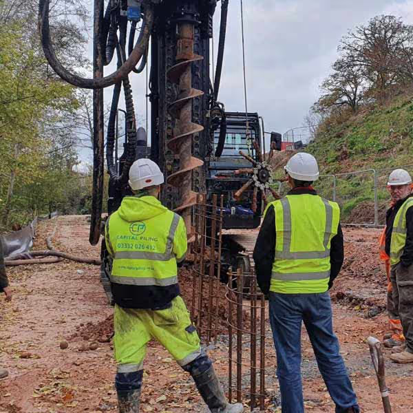
The reinforcement cage is designed by the structural engineer based on the loads the pile needs to carry and the forces it will experience in the ground. It consists of longitudinal bars arranged in a circular pattern held in position by helical binding wire or links wrapped around the outside at regular intervals. The cage is fabricated to the dimensions shown on the structural engineer's drawings and must fit within the pile diameter with sufficient concrete cover maintained on all sides.
Minimum concrete cover to the outside face of the reinforcement cage in a CFA pile is 75mm as specified in BS EN 1536. This cover protects the steel from corrosion over the design life of the pile and must be maintained consistently around the full perimeter of the cage using correctly positioned spacers. The cage must also project sufficiently above the pile head to provide the lap length required when the ground beam or pile cap is cast above.
How the reinforcement cage is designed, fabricated and installed
The structural engineer calculates the reinforcement requirements based on the axial loads, bending moments, and shear forces the pile needs to resist. In a straightforward vertically loaded pile, the cage may be relatively lightly reinforced. Where the pile is subject to significant lateral loads, bending from ground movement, or tension forces, the reinforcement requirements increase accordingly and the cage design becomes more detailed.
Once the design is complete, the cage is fabricated either off site or on site to the specified dimensions. Longitudinal bars are cut to length, arranged at the correct spacing around the perimeter, and the helical binding wire is wound around them and tied or welded at intervals to hold the bars in position. Concrete cover spacers are fitted around the outside of the cage to maintain the correct standoff from the pile bore wall.
After the CFA auger has been withdrawn and the bore is filled with concrete, the cage is lowered or vibrated into the wet concrete to the specified depth. Timing is critical at this stage. The concrete must still be sufficiently workable to allow the cage to reach the required depth. If the mix begins to stiffen before the cage is fully placed, the pile may need to be rejected and replaced, which is a costly and avoidable outcome with the right planning and coordination on site.
How reinforcement requirements vary across different project types and loading conditions
On a lightly loaded residential pile carrying primarily vertical axial load, a relatively simple cage with a modest number of longitudinal bars at moderate diameter is typically sufficient. On a commercial project with high column loads, significant bending moments, or lateral forces from retained ground or wind loading transferred through the structure, the cage design becomes considerably more complex and the reinforcement quantities increase significantly.
Where piles are used to support retaining walls, basement structures, or ground beams spanning significant distances, the cage may need to extend further up the pile than would be required for a purely axially loaded element. In these situations the interface between the pile reinforcement and the ground beam or wall reinforcement above needs to be carefully detailed to ensure the structural continuity required to transfer the full range of forces involved.
The technical specifications that govern CFA pile reinforcement cage design
Reinforcement bars used in CFA pile cages are typically high yield steel to Grade 500B in accordance with BS 4449. Bar diameters commonly range from 16mm to 40mm for the main longitudinal bars depending on the structural loads, with helical binding wire typically between 8mm and 12mm diameter. The number of longitudinal bars and their spacing around the perimeter are determined by the structural design and must be consistent with the minimum and maximum reinforcement ratios specified in BS EN 1536 and the relevant Eurocode.
Cage length is determined by both the structural requirements and the connection detail at the pile head. The projecting bars above the cut pile head must achieve the required tension lap length within the ground beam or pile cap above, which is typically calculated as 40 to 50 times the bar diameter depending on the concrete grade and the cover conditions within the receiving element.
What can go wrong with reinforcement cage design and installation and how to avoid it
Cage fabrication quality needs to be checked before installation begins. Bars that are out of position, incorrect cover spacers, wrong cage diameter, or insufficient projection above the pile head can all cause problems during placement or affect the structural performance of the finished pile. These are issues that are straightforward to identify and correct before the cage goes into the ground and very difficult to address afterwards.
The window between the auger being withdrawn and the concrete beginning to stiffen is short, and the cage needs to be ready and positioned correctly before that window closes. Poor site organisation, delays in cage delivery, or cages that are the wrong length or diameter are all avoidable problems that come down to preparation and coordination. On projects where Capital Piling is delivering the full foundation package including ground beams and RC slabs, the reinforcement design for the piles and the connecting elements above is coordinated as a single exercise, which means the cage specifications, projection lengths, and connection details are all resolved before a single pile is installed rather than picked up as problems on site.