What reinforcement requirements mean in ground beam and RC slab construction and why getting them right is one of the most consequential decisions in the entire foundation design process
Reinforcement requirements define the type, size, quantity, spacing, and positioning of the steel bars or fabric mesh that must be placed within a ground beam or RC slab to enable that element to carry the loads applied to it safely, without cracking beyond acceptable limits, and without deflecting to a degree that affects the performance of the structure above. They are the output of the structural design process and they are specific to the project, the element being designed, and the loads and ground conditions applicable to that project. They cannot be assumed, carried over from a previous project, or reduced to save cost without a full structural reassessment of the consequences.
The role of reinforcement in a concrete structural element is to carry the tensile forces that concrete alone cannot resist. Concrete is strong in compression and weak in tension. In a ground beam subject to bending under load, one face of the beam is in compression and the other is in tension. Without reinforcement in the tension zone the beam will crack as soon as the tensile stress in the concrete exceeds the tensile strength of the mix, which under structural loads it invariably will. The reinforcement prevents that cracking from becoming structurally significant by carrying the tension across the crack and maintaining the integrity of the beam section under load. The area of reinforcement required to do this is what the structural design calculation establishes, and placing less steel than the calculation requires is not a minor variation. It is a structural deficiency that will manifest as cracking, deflection, or failure under the loads the element was designed to carry.
The types of reinforcement used in ground beams and RC slabs and what each type contributes to the structural performance of the element
Longitudinal reinforcement in a ground beam consists of bars running along the length of the beam in the tension and compression zones. The tension steel carries the tensile forces generated by bending, and its area is determined by the maximum bending moment in the beam and the lever arm available between the tension and compression zones at the critical section. The compression steel, where provided, assists the concrete in carrying compression at sections where the bending moment is high and the concrete compression zone alone is insufficient to carry the full compression force within the available beam depth.
Shear reinforcement in a ground beam consists of links or stirrups, closed loops of bar that surround the longitudinal reinforcement and are spaced along the beam length at intervals determined by the shear force diagram. Their function is to carry the diagonal tension forces generated by shear in the beam web, preventing diagonal cracking between the compression and tension zones that would compromise the beam's ability to transfer load to the pile head support positions. Link spacing is closest in the high shear zones adjacent to pile heads and may be relaxed towards mid-span where shear forces are lower, but the design must confirm the required spacing at every critical section rather than applying a uniform spacing throughout.
Reinforcement in an RC slab consists of bars or fabric mesh placed in two orthogonal directions to carry the bending moments in both span directions. In a two-way spanning slab the reinforcement in each direction is proportioned to the moments in that direction, with the heavier reinforcement in the direction of the shorter span where the moments are typically higher. In a one-way spanning slab the primary reinforcement runs in the span direction and the secondary or distribution reinforcement runs perpendicular to the span, carrying a minimum proportion of the primary steel area to control cracking and distribute concentrated loads.
How reinforcement requirements are established during the structural design process and how the specified reinforcement is placed and fixed during construction
The reinforcement design begins with the bending moment and shear force diagrams produced from the structural analysis of the beam or slab under the critical load combinations. From the maximum bending moment at each critical section the engineer calculates the required area of tension reinforcement using the design equations in BS EN 1992, selecting bar diameters and spacings from the standard range that provide at least the required area while remaining practical to place and fix within the beam or slab geometry with the required cover maintained throughout.
The shear reinforcement design follows from the shear force diagram, with the required link area per unit length calculated at each critical section and converted to a link diameter and spacing from the standard bar range. Where the shear force is high enough that links alone cannot provide the required shear resistance within the beam geometry, the beam dimensions may need to be increased, or the pile spacing reduced to lower the shear force, rather than attempting to overcome the deficiency with reinforcement alone.
Once the reinforcement has been designed it is detailed on drawings that show the bar sizes, spacings, laps, and cover dimensions at every position in the element. These drawings are the instructions that the reinforcement placers work from on site, and they must be sufficiently clear and complete that the reinforcement can be placed correctly without reference back to the design engineer for clarification at every stage. Reinforcement that is placed incorrectly, at the wrong cover, in the wrong position, or with inadequate laps between bars, does not perform as the design assumes, and the structural consequences of misplaced reinforcement can be as serious as those of insufficient reinforcement.
How reinforcement requirements vary across different ground beam and slab applications and what drives the differences in steel quantity between residential and commercial projects
On a residential ground beam the reinforcement typically consists of two or three longitudinal bars top and bottom in sizes ranging from 12mm to 20mm diameter, with links of 8mm or 10mm diameter at spacings that reflect the shear force diagram for the beam. The total steel quantity in a residential ground beam is modest relative to the beam volume, but it is no less carefully calculated for that. The bars must be the right size, in the right position, with the right cover, and with laps of the correct length wherever one bar ends and another begins.
On a commercial ground beam carrying concentrated column loads or spanning greater distances between pile caps, the reinforcement demands are considerably higher. Multiple layers of large diameter bars in the tension zone, closely spaced links in the high shear zones adjacent to pile cap support positions, and additional torsion reinforcement where the beam is subject to eccentric loading are all features of commercial ground beam reinforcement that go well beyond what a residential detail would contain. The detailing of this reinforcement must be carried out carefully to ensure that the bars can be placed and the concrete can be compacted around them, because congested reinforcement that prevents adequate concrete compaction is as problematic as insufficient reinforcement.
On an RC slab the reinforcement requirements vary from the relatively light fabric mesh used in lightly loaded residential slabs to the heavy bar reinforcement used in industrial floor slabs carrying forklift traffic and high point loads from racking systems. The transition between these extremes reflects the wide range of imposed loads that RC slabs are designed to carry across different construction sectors, and the reinforcement specification for any given slab must reflect the actual imposed loads for that project rather than an assumed standard.
The minimum reinforcement requirements set by BS EN 1992, the cover rules that govern bar positioning, and the lap length and anchorage requirements that ensure continuity of force transfer through the reinforcement
BS EN 1992 sets minimum reinforcement requirements for concrete beams and slabs that apply regardless of what the structural analysis produces. For beams, the minimum area of tension reinforcement is a function of the mean tensile strength of the concrete and the cross sectional area of the beam, and it is intended to ensure that the beam has sufficient ductility to redistribute moments after first cracking rather than failing suddenly without warning. For slabs, minimum reinforcement requirements ensure that the slab can carry the loads associated with shrinkage and temperature effects in addition to the structural loads, preventing uncontrolled cracking that would be unacceptable in service.
Cover to reinforcement in ground beams cast against the ground is a minimum of 75mm to the outermost bar, as specified in BS EN 1992 and the UK National Annex. This cover requirement is greater than the cover needed for durability in a normal above ground exposure condition, reflecting the more aggressive exposure conditions at the beam soffit in contact with the ground and the greater uncertainty about the surface regularity of an excavated trench compared to a formed surface. Spacers must be used throughout the reinforcement cage to maintain the specified cover at every position, and the spacer specification and spacing must be appropriate to the bar sizes and cage weight involved.
Lap lengths and anchorage lengths for reinforcement bars must be calculated in accordance with BS EN 1992 and stated clearly on the reinforcement drawings. A lap that is shorter than the required length cannot transfer the full design force between bars, and an anchorage that is shorter than required cannot develop the full bar force at the point where it is needed. Both are common sources of cracking and structural inadequacy in ground beams and slabs built without adequate attention to the detailing requirements.
What can go wrong when reinforcement requirements are not properly established or not properly followed during construction and what the consequences are for the structural performance of the foundation
The most common reinforcement related problems in ground beam and RC slab construction are insufficient cover leading to corrosion of the reinforcement over time, misplaced bars resulting in reduced lever arm and reduced bending resistance, inadequate lap lengths causing loss of force transfer continuity through the reinforcement, and omitted links in high shear zones leaving the beam vulnerable to diagonal cracking under load. Each of these problems is preventable through proper design, proper detailing, and proper supervision of the reinforcement placement during construction.
Reinforcement corrosion is a long term problem that becomes apparent years or decades after construction when the expanding corrosion products crack the concrete cover and the bars lose their cross sectional area. By that point the structural performance of the beam or slab may have been compromised to a degree that requires significant remedial intervention, and the cost of that intervention is many times greater than the cost of maintaining the specified cover during original construction. Cover is not a dimension that can be reduced for convenience during placing without consequences, and this needs to be understood and enforced by everyone involved in the construction process.
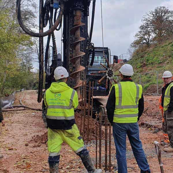
Capital Piling places and fixes all reinforcement for ground beams and RC slabs in accordance with the structural drawings and the requirements of BS EN 1992, with cover maintained throughout using correctly specified spacers and the reinforcement checked against the drawings before concrete is placed. Where discrepancies between the placed reinforcement and the drawing requirements are identified during the checking process they are corrected before concreting proceeds, ensuring that the foundation is built to the reinforcement specification the structural design requires rather than to whatever happened to be placed in the trench on the day.