What the typical diameter range for mini piles is and why diameter selection is an engineering decision driven by loads and ground conditions rather than a standard choice applied uniformly across all projects
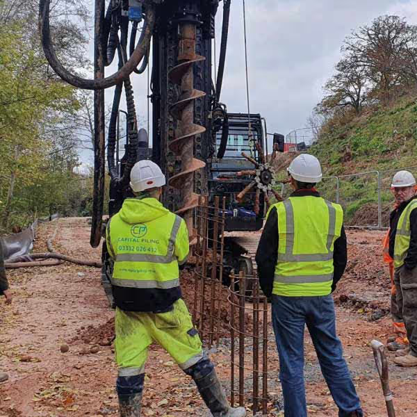
Mini pile diameters at Capital Piling range from 150mm at the lower end for lightly loaded residential and temporary applications through to 450mm at the upper end for more heavily loaded commercial and residential development projects. Within this range the specific diameter selected for any given project and any given pile position is determined by the structural load that pile must carry, the ground conditions it will be installed into, the depth at which competent bearing strata are available, and the access and equipment constraints that apply on the specific site. It is not selected from a preferred list or assumed from what was used on a previous project with superficially similar characteristics.
Diameter is one of the most consequential decisions in mini pile design because it directly affects the shaft friction available along the pile length, the end bearing resistance at the pile toe, the volume of grout or concrete required to complete the pile, and the installation time per pile. A diameter that is too small for the loads and ground conditions will produce a pile that cannot carry the design load without excessive settlement or outright failure. A diameter that is larger than necessary increases the cost of each pile without delivering structural benefit and may compromise the access advantages that mini piling offers on constrained sites by requiring a larger bore that takes longer to advance and produces more spoil.
How the available diameter range relates to structural capacity and what drives the selection of a specific diameter for a given pile position
At the lower end of the diameter range, piles of 150mm to 200mm diameter are used on lightly loaded residential applications where the structural loads at individual pile positions are modest and the ground conditions allow capacity to be developed within a practical pile length. These smaller diameters are also used on temporary works applications where the pile is required to carry load for a defined period rather than for the full design life of a permanent structure, and on projects where the access constraints are so severe that even the bore diameter makes a practical difference to what the installation equipment can achieve within the space available.
In the mid-range between 200mm and 350mm, mini piles carry the working loads typical of most residential new build and extension projects, light commercial structures, and infrastructure applications where column or wall loads are within the range that this diameter can accommodate efficiently in typical UK ground conditions. This is the diameter range most commonly encountered on residential mini piling projects across London and the south east, where the combination of modest structural loads, restricted access, and cohesive London Clay ground conditions at workable depths makes piles in this size range the standard design outcome.
At the upper end of the range from 350mm to 450mm, mini piles approach the capacity of small diameter CFA piles and are used on projects where the structural loads are at the higher end of what mini piling equipment can deliver, where the ground conditions require a larger bearing surface to develop the required capacity within a practical pile length, or where the structural engineer has determined that fewer, larger diameter piles are more efficient for the specific pile layout than a greater number of smaller diameter piles carrying lighter individual loads.
How the diameter is determined during the design process and how it influences every other aspect of the pile specification
The diameter determination process begins with the load at each pile position and the soil parameters from the ground investigation. The structural engineer calculates the shaft friction available per unit length and the end bearing resistance available at the target founding depth for a trial diameter, sums these contributions to give the total ultimate capacity, applies the required factor of safety to establish the working capacity, and compares that working capacity to the design load at the pile position. Where the working capacity of the trial diameter exceeds the design load with the required margin, that diameter is potentially adequate. Where it does not, the diameter is increased, the depth is increased, or both, until the required capacity is achieved.
This calculation is carried out for each pile position on the project where the load or the ground conditions differ from adjacent positions, because the optimum diameter for one pile position may not be the optimum for another where the load is different or where the soil profile has changed. On projects with a uniform structural load and a consistent soil profile, a single diameter may be adequate throughout. On projects with variable loads or variable ground conditions, a range of diameters may be used across the pile layout to optimise the foundation cost and performance at each position individually rather than applying a conservative uniform specification to all positions.
The selected diameter also influences the equipment required for installation. Larger diameter bores require more torque from the rotary head or more energy from the percussive system, and the equipment must be capable of advancing the bore to the required depth and diameter in the ground conditions encountered. Equipment selection must therefore be confirmed alongside the diameter selection rather than after it, to ensure that the machine specified for the project can install the piles the design requires within the access and headroom constraints that apply.
How diameter requirements vary across different project types and what the typical diameter outcomes are for common mini piling applications
On a two storey residential extension in London Clay with pile positions beneath the perimeter ground beam at two to three metre centres, pile diameters of 200mm to 300mm at depths of seven to twelve metres are a common design outcome. The wall loads from a two storey structure are modest, London Clay provides reliable shaft adhesion over the pile length, and the combination of diameter and depth produces working capacities that comfortably exceed the design loads at individual pile positions without requiring the larger diameters that would add unnecessary cost to a straightforward residential project.
On a three or four storey residential development or a light commercial structure with higher column or wall loads, diameters of 300mm to 400mm at greater depths are more typical, reflecting the increased loads and the need for greater shaft friction area and toe bearing resistance to develop the required capacity within a practical pile length. On these projects the pile layout may also include variations in diameter between more and less heavily loaded positions, with larger diameter piles beneath the highest load positions and smaller diameters elsewhere.
On basement underpinning projects where the pile must be installed within a confined basement environment and the headroom limits the drill string length and the bore diameter that can be advanced in a single setup, the diameter is often constrained by the equipment configuration as well as by the structural load, and the design must work within both sets of constraints simultaneously to arrive at a practical and structurally adequate specification.
The relationship between diameter, shaft friction, end bearing, and pile capacity across the mini pile diameter range and the standards that govern diameter selection
The capacity of a mini pile increases with diameter through two mechanisms. Shaft friction increases because the pile perimeter increases with diameter, providing more surface area over which the unit shaft friction can act along the pile length. End bearing increases because the pile toe area increases with the square of the diameter, providing a greater bearing surface at the founding level. Both contributions increase with diameter, but they do so at different rates, and the relative importance of each depends on the pile length and the soil profile.
In cohesive soils such as London Clay, shaft friction is the dominant capacity mechanism for mini piles at the depths typically used in residential and light commercial applications. The unit shaft friction in London Clay is a function of the undrained shear strength, which increases with depth, and the shaft friction contribution is calculated by integrating the unit shaft friction over the full embedded pile length. Increasing the diameter increases the pile perimeter and therefore the total shaft friction for a given length, with the increase in capacity proportional to the increase in perimeter rather than the increase in cross sectional area.
In granular soils where end bearing is a more significant contribution to total pile capacity, the diameter increase has a greater proportional effect on capacity because the toe area increases with the square of the diameter. A pile of 300mm diameter has a toe area approximately 2.25 times that of a 200mm diameter pile, and in granular ground where end bearing is significant this difference translates directly into a meaningful increase in the end bearing contribution to total capacity.
What needs to be confirmed before the pile diameter is finalised and what the consequences are of selecting a diameter without proper geotechnical analysis of the site specific conditions
Pile diameter cannot be reliably selected without a ground investigation that provides the soil parameters needed to calculate shaft friction and end bearing at the target founding depth. A diameter selected on the basis of assumed or typical soil properties rather than measured site specific data carries a risk that the actual capacity in the ground conditions encountered during installation will differ from the design assumption, producing piles that either cannot reach the required torque or grout acceptance criterion at the target depth or that develop less capacity than the design assumed at that depth.
Where ground conditions vary laterally across the site, the diameter selection must account for that variation explicitly rather than applying a single diameter based on the most favourable borehole location across the full pile layout. Piles installed in weaker ground than the design assumed will be under-capacity at the specified diameter and depth, and this under-capacity will not necessarily be apparent from the installation records unless the acceptance criteria have been set to reflect the actual ground conditions at each pile position rather than the average conditions across the site.
Capital Piling selects pile diameters as part of an integrated design process that begins with the ground investigation data and the structural load schedule and produces a pile specification in which every diameter is calculated for the actual conditions at the specific pile positions it applies to. This means the diameter specified for each position is the one that delivers the required capacity in the ground that is actually there, verified against the installation records produced during the works, and documented in the completion records issued to the structural engineer and client at the end of the project.