What ground beams are and why they are a fundamental part of the piled foundation system rather than a separate structural element
A ground beam is a reinforced concrete beam cast at or just below ground level that spans between pile heads and distributes the loads from the structure above into the piles below. It is the structural link between the foundation and the building, and on a piled foundation it performs a role that is often underestimated in its importance. Without a properly designed ground beam, the loads from walls, columns, and floor slabs cannot be transferred efficiently into the pile heads, and the piles themselves, however well designed and installed, cannot perform the function the foundation design requires of them.
Ground beams are used on piled foundations across a wide range of project types, from residential extensions and new build houses through to commercial steel frame buildings and industrial structures. They are cast in situ using reinforced concrete, formed in excavated trenches or against temporary formwork, and designed by the structural engineer to carry the specific loads at each beam position while spanning efficiently between the pile heads that support them. The beam geometry, the reinforcement arrangement, and the connection detail at each pile head are all engineered outputs specific to the project, and they cannot be assumed or standardised across different sites without a proper structural assessment.
Why ground beams are specified on piled foundations and what they do that other foundation elements cannot
Ground beams serve two functions simultaneously. They transfer vertical loads from the structure above down into the pile heads below, and they tie the pile heads together so that the foundation behaves as a coordinated structural system rather than a collection of independent elements. This tying function is particularly important on piled foundations where the piles are subject to lateral loads or differential settlement, because the ground beams provide the horizontal restraint that prevents individual piles from moving independently of their neighbours.
On a strip foundation bearing directly on the ground, the load from the wall above is distributed along the length of the strip into the soil beneath it. On a piled ground beam foundation the load path is different. The wall or frame element above bears onto the ground beam, the ground beam spans between pile heads and concentrates the load at those points, and the piles carry that concentrated load down through weak or compressible upper strata to the competent bearing stratum at depth. The ground beam is therefore not just a connection detail. It is a structural element that must be designed for the bending, shear, and torsion it will experience in service, and it must be strong enough to carry those effects without cracking, deflecting excessively, or failing under the design loads.
How ground beams are designed, formed, reinforced, and cast as part of the piled foundation system
The design of a ground beam begins with the structural loads from the building above and the pile layout below. The structural engineer calculates the bending moments and shear forces in the beam for the load combinations applicable to the design, selects a beam cross section that can carry those effects within acceptable stress limits, and designs the reinforcement arrangement needed to provide the required bending and shear resistance. The beam depth and width are determined by the structural demands rather than by convention, and on projects where loads are high or pile spacings are large the beam cross section can be considerably deeper than the standard profiles used on lightly loaded residential work.
The beam is formed in a trench excavated between pile positions, with the sides of the trench acting as permanent formwork where the ground is stable enough to allow this. Where the trench sides cannot be relied upon to maintain their profile, temporary formwork is used to define the beam geometry. The reinforcement cage is placed into the formed trench, connected to the pile head reinforcement or starter bars projecting from the pile cap, and checked for cover and position before concrete is placed. Concrete is poured continuously along the beam length to avoid cold joints, compacted by vibration, and cured before the formwork is struck and the beam is loaded.
The project types and structural situations where ground beams are the appropriate connection between piles and superstructure
Ground beams are used on virtually all piled foundations where the structure above is a load bearing wall, a masonry or timber frame building, or any structural system that applies load as a distributed line rather than as discrete point loads at column positions. On residential new build and extension projects, ground beams running beneath all load bearing walls and connecting all pile heads are the standard foundation arrangement, providing continuous support to the wall construction above and tying all pile heads together into a coherent foundation system.
On commercial projects with steel or concrete frames, ground beams may be used to connect pile caps beneath column positions, to support ground floor slab edges, or to carry non-structural infill panels between column bases. Where column loads are concentrated at discrete positions, pile caps rather than continuous ground beams may be used beneath each column, but the principle of connecting pile heads through a reinforced concrete element and tying them together structurally remains the same regardless of whether that element is described as a ground beam or a pile cap.
The structural and geometric parameters that define a ground beam and the standards that govern its design and construction
Ground beam cross sections on residential projects typically range from 300mm wide by 450mm deep for lightly loaded beams on short spans up to 450mm wide by 600mm deep or more for beams carrying heavier wall loads or spanning greater distances between pile heads. On commercial projects beam dimensions are determined by the structural analysis and can be considerably larger than these indicative ranges where loads or spans demand it.
Reinforcement in a ground beam comprises longitudinal bars providing bending resistance, typically in two layers top and bottom with the bar size and spacing determined by the bending moment diagram for the beam, and links or stirrups providing shear resistance at the required spacing along the beam length. Minimum concrete cover to the outermost reinforcement in a ground beam cast against the ground is 75mm in accordance with BS EN 1992, and this cover must be maintained throughout the beam using correctly positioned spacers on the reinforcement cage before concrete is placed.
Concrete specification for ground beams is typically a designed mix to a minimum strength class of C25/30, with the mix design reviewed for sulphate resistance where the ground investigation has identified sulphates in the soil or groundwater. Where aggressive ground conditions require it, a higher sulphate resisting mix or a protective membrane between the beam soffit and the ground may be specified.
What needs to be resolved before ground beam construction begins and the consequences of poor coordination between the piling and ground beam design
Ground beam construction cannot begin until the pile heads are at the correct level and position to receive the beam reinforcement and to provide the structural connection the design requires. Where pile heads are outside the positional or level tolerances stated in the specification, the ground beam design must be reviewed before construction proceeds to confirm that the beam can accommodate the deviation without compromise to its structural performance. Casting a ground beam over pile heads that are outside tolerance without a structural review is not acceptable and can result in a connection that does not perform as designed under load.
The interface between the pile design and the ground beam design must be fully coordinated before either element is constructed. The pile head level determines the soffit level of the ground beam. The pile cap or head reinforcement detail determines how load is transferred from the beam into the pile. And the pile positions determine the span lengths the beam must be designed to carry. Where these elements have been designed by different engineers or specified at different stages of the project without coordination, conflicts at the interface are common and can be costly to resolve once the piles are in the ground.
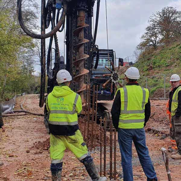
Capital Piling designs and installs piled foundations as a fully integrated service, with ground beam design carried out alongside the pile design as part of a single coordinated package. This means the pile head levels, connection details, and beam geometry are all resolved together before any construction begins, and the foundation is built to a fully coordinated design rather than assembled from separately produced components that have not been checked against each other.